
Click here to view the document as a PDF.
TECHNICAL SPECIFICATION OF MITSUBISHI BASIC DIESEL GENERATOR SET
This specification covers the indoor use MITSUBISHI diesel engine generator set and attached equipment.
Note 1 For actual voltage and output, refer to the “Scope of supply” sheet
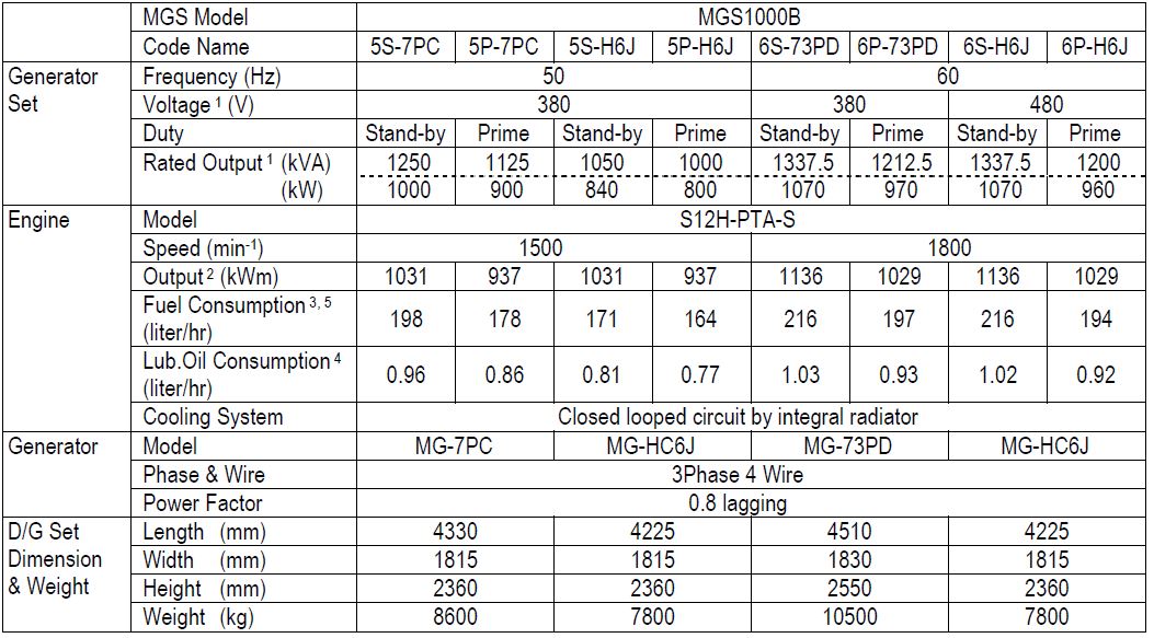
Note 2 Output at 40 deg C , 1000m ASL with Fan
Note 3 Fuel Consumption at 75% Load
Note 4 Lub. Oil Consumption at 100% Load
Note 5 Fuel Consumption may differ subject to site condition and specification of fuel.
Not guaranteed value

1. BASIC CONDITIONS
1.1 MEASUREMENT
Unit of measurement, weight, and capacity concerning all of the equipment supplied by us, SI unit and English letter are used.
1.2 SHOP TEST
Diesel generator test shall be carried out on the following items at the manufacturer's shop.
(1) Starting and stopping test.
(2) Load test
(3) Governor test.
(4) Insulation and alarm test.
Generator and switchboard test shall be carried out at generator manufacturer's shop. After the test, the test record shall be submitted.
1.3 Applicable standard
To be in accordance with JIS, JEC, JEM, IEC and manufacturer’s standards unless otherwise specified
a) J.I.S. : Japanese Industrial Standards
b) J.E.C. : Standard of the Japanese Electrotechnical Committee
c) J.E.M. : The standard of Japanese Electrical Manufacturers Association
d) I.E.C. : International Electrotechnical Commission
e) I.S.O. : International Organization for Standardization
1.4 GUARANTEE
The guarantee shall be valid for the period of twelve (12) calendar months after completion of commissioning test at site or for the period of eighteen (18) calendar months after B/L date, whichever comes earlier. The guarantee shall cover against manufacturer defect, bad materials and workmanship only, and shall not be applicable to damage sustained through mishandling of the equipment and force majeure. The guarantee shall not be liable for any consequential or resultant loss or damage howsoever occurring. The guarantee shall be subject to the proper maintenance of machinery and equipment according to the maintenance schedule to be submitted separately.
1.5 PAINTING
Mitsubishi standard (Dark Blue) Munsell 6.0PB 4.4/5.2
1.6 ENVIRONMENT ETC.
Generator sets are designed under the following operating conditions
a) Relative humidity : Max. 85%
b) Ambient temperature : 40deg.C
c) Altitude above sea level : Below 1000 meters
2. DIESEL ENGINE
2.1 Particulars of diesel engine

2.2 Engine Instrument
Engine instruments shall be installed in the generator panel.
Engine status are showed by graphical icon and digital indicator on LCD display of the generator panel.
3. AC GENERATOR
The brushless AC Generator coupled with the diesel engine and installed onto a common bed.
The AC Generator provided the following characteristics.
3.1 Particulars of the AC Generator
(1) Standard specification
Type: Brushless, self excited, self ventilating and rotating field
Protection: IP23
No. of pole: 4 pole
Insulation : Class "H"
Excite: Brushless
Bearing : Single ball bearing
3.2 Characteristics (AC Generator)
(1) Steady state voltage regulation
Voltage Regulation will be ± 0.5% when the load
varies between no load and full load at power factors between 0.8 and
1.0 over a prime mover speed range of 4%
(2) Transient Response
The Instantaneous Voltage Regulation will be within 25% and recoverable to within 3% of the final steady-state voltage in not more than 1sec., when full load at a power factor of 0.4 or less is suddenly applied to the AC Generator running at no load and rated frequency. However engine response may influence on recovery time.
(3) Voltage wave form
The wave form deviation of phase to phase voltage, as checked at the
AC Generator terminals, is not greater than 5% at no-load rated voltage.
(4) Unbalanced loading
An acceptable value of negative phase sequence current is approximately 8% of rated current. Up to 25% load imbalance can be tolerated on a continuous basis.
(5) Temperature rise limits
The main windings of the AC Generator are designed for operation to Class H temperature rise limits.
(6) Insulation strength
The dielectric strength of the winding insulation system is checked during manufacture by conducting a High Voltage withstand test.
Main Stator winding: AC 2000V Main Rotor winding: AC 1500V
(7) Overspeed
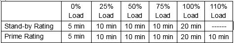
The AC Generator is capable of withstanding overspeeds to 125% of the rated speed for two minutes under no load.
(8) Voltage adjustment is typically ± 6% using a remotely connected trimmer.
(9) Terminal box
The large fabricated sheet steel terminal box mounted on the AC Generator accommodates load output terminals and access cover.
4.GENERATOR CONTROL ( MGS7310GCP )
4.1 General
Automatic start engine management and instrumentation system module
in fabricated cubicle is installed on individual bracket with anti-vibration isolator.
4.2 Instruments and control accessories
Instruments are graphical icon on LCD display
a) Generator running indicator
b) Voltage adjuster
c) Frequency adjuster
d) Emergency stop switch
e) Selector switch (STOP / RESET , ACTIVE , PANEL LOCK)
f) Manual start button
g) Manual stop button
h) Common alarm indicator
i) Transfer to generator button (manual mode only)
j) Transfer to main button (manual mode only)
k) Mute alarm button
l) Manual Mode button
m) Auto Mode button
n) Menu navigation buttons
o) Alarm indication on LCD (see 4.3)
p) Status indicator (see 4.5)
q) Value display on LCD
1) Frequency / RPM
2) AC voltage phase
3) AC voltage phase-phase
4) AC Line Current
5) Oil pressure
6) Coolant temperature
7) Oil temperature λ
8) Engine hours run
9) DC battery voltage
10) Generator frequency
11) Generator load / kW
12) Generator load / kVA
13) Power factor / pf
14) Generator load / kVAr
15) Generator load / kWh, kVAh, kVarh
16) Generator phase sequence
17) Generator Nominal
18) Exhaust gas temperature ※λ
19) Winding temperature (U,V,W) ※λ
20) Bearing temperature ※λ
※ These values shall be displayed on the alarm box adjacent to MGS7310GCP
λ Optional item upon request
4.3 Fault operation
Fault operations shall be provided as follows;
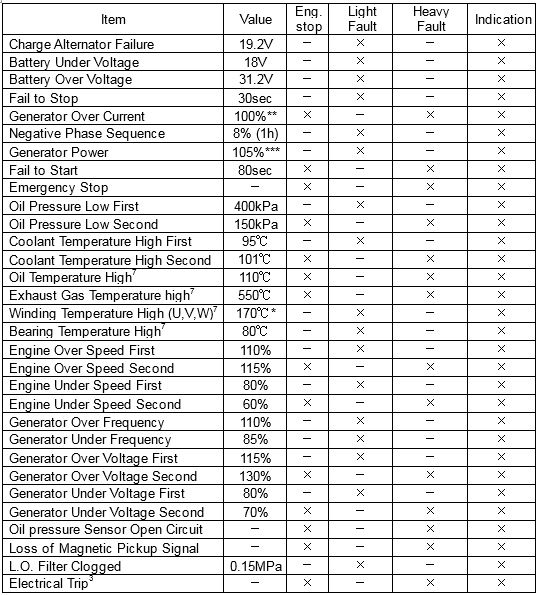
NOTE : 1. “×” marks are applicable items.
2. “-” marks are not applicable items.
3. Eng stop by Electrical trip signal will be done after Eng cooled.
4. Regarding *, in case of “Prime” duty, that value is 150℃
5. Regarding **,in case of “Prime” duty that value is 110%
6. Regarding ***,in case of “Prime” duty that value is 115%.
7. Optional items installed upon request.
4.4 Auxiliary input signals
If the functions as follows are necessary, please input external command signals to the control panel.
(1) Remote start/stop
(2) Electrical trip
(3) CB close status (Generator closed auxiliary)
4.5 Status indicator
(1) Remote start present
(2) Generator ready
(3) LO filter clogged
(4) Electrical trip
4.6 Auxiliary output signals
These signals are output from control panel as 24V DC .
(1) COMMON Shutdown alarm signal (for CB Trip)
(2) kW Overload alarm
(3) Low speed detection
(4) CB close command (pulse)
(5) CB open command (pulse)
(6) AUTO Mode
(7) Common Electrical Trip ※
(8) Energize to stop ※
(9) Common warning ※
(10) Failed to start alarm ※
(11) Over speed shutdown ※
(12) Emergency stop ※
(13) Low oil pressure ※
(14) High water temperature ※
※ Require optional 2157 relay unit
4.7 Operation
Generator control panel has three positions of key switch. Each position is written in below.
・STOP / RESET : Engine stop and controller reset operation are available.
・ACTIVE : Auto and manual mode can be selected by auto and manual button on controller.
・PANEL LOCK : Even if auto or manual button is pushed, mode selection is not applicable.
Engine start and stop shall be done by operator. When engine trouble occurred engine should be stopped by generator panel automatically.
Remote start and stop control are available, when auto mode is selected by auto mode button.
5. LIMITING REQUIREMENT FOR FUEL OIL, COOLANT AND LUBRICATION OIL
5.1 Fuel system
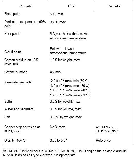
Fuel to meet ASTM D975 grade No.2-D or BS2869 class A or JIS K-2204. (APPENDIX-1)
Fuel tank and fuel pipes to be free of dirt, water or other foreign substances.
5.2 Cooling system
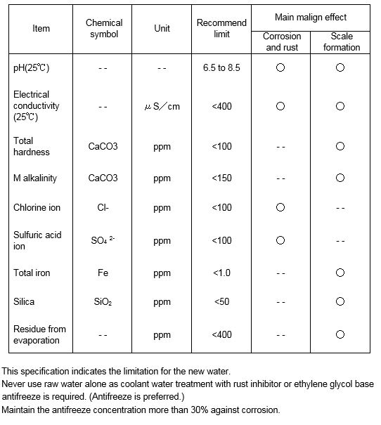
Coolant to meet the coolant specifications. (APPENDIX-2)
5.3 Lubrication system
Engine oil to meet API service classification CD or CF. (APPENDIX-3)
Do not use CE and CF-4 lube oils for Mitsubishi high-speed diesel engines.
- End of Specification -
APPENDIX-1
Limiting Requirements for Mitsubishi Diesel Fuel oils
APPENDIX-2
Coolant Specifications
APPENDIX-3
Recommended Lubricating Oil
